The software components involved in developing the ECU can be divided into two parts – infrastructure (BSW) and application. Application is what the company is ready to pay for. Before AUTOSAR one application was attached with one ECU. This is because the software (Application) was tightly coupled with the infrastructure (BSW) and the hardware. One of the major features supported by the software Architecture of AUTOSAR is the scalability and flexibility it provides to software development. If we have an interface that can separate the application from the infrastructure and if the interface can effectively communicate between the application and the Basic software; the application team can focus more on the application development.
This expands the growth of the business opportunity. If you are a software company and your strength is on developing a particular application, say for instance, airbag Application, then the company can focus on developing AIRBAG application. If the interface(AUTOSAR interface) can couple your application with the Electronic Control Units of many vendors then your scope of business increases dramatically. The Tier1 can focus on developing the BSW. The OEM can retain the IP of developing the infrastructure in house (or) the OEM may develop the Application which they don’t want share with the TIER1. For instance, Ferrari may develop an algorithm that they may use to control the speed of the car. Ferrari may not want to share the algorithm. Once the interface is negotiated then the Ferrari can go and decide the supplier that will supply the ECU. This provides a huge flexibility options for the OEM and Tier1 company to focus on exclusive software components that they care about.

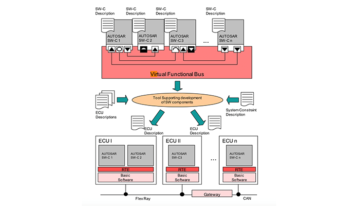
A detailed view of the AUTOSAR configuration system is illustrated in the Figure.
Model based software design and Virtual Function Bus
The application layer is working on the topmost component. The objective is to build individual software components that can effectively communicate with the other software components. The application is developed independent of the infrastructure, independently of the execution platform. Think of an application that you have to develop. Just focus on how the controller should be mapped, partitioning the s/w components and how they interact, design the software components and dont worry about the infrastructure. When the definition of the application is good we can implement them on the execution platform.
AUTOSAR provides a high flexibility of implementing the s/w through deployment tools. For example, OEM tells the supplier(Tier1) that we have to develop 3 s/w components for a particular application and the s/w components have to be distributed among three ECUs. Then we will decide which are the three s/w components and the ECUs in which they have to be deployed and the protocol/channel through which they will interact and the gateway facilitating the communication. Then we have to decide the system constraints and also the ECU constraints like the amount of memory available and what are the functions that has to be done by the ECU.
If another OEM says that they want all the 3 s/w modules to be implemented in a an single ECU then again the application need not be changed. Though the system and ECU constraints are different. the deployment tool takes care of mapping the communication between the s/w components .Implementing the same principle in multiple hardware is totally automated.
Let us say there is a company in Europe developing algorithms to control diesel engines. Europe has 4 cylinders , other countries may have different number of cylinders. The infrastructure to run the application is different in different in different continents. AUTOSAR can make it easy. In Europe they may use a diesel engine, other continents may design a gasoline engine but both have some same s/w components. They can be interchangeably used. AUTOSAR just does not reduce the cost of the hardware but it also manages the complexity .
AUTOSAR s/w components
As discussed, the application software can be broken into smaller modules (atomic module). A single s/w component (atomic) is mapped only in one ECU . The application may be distributed among different ECUs but a single component cannot be further divided. It has to be mapped to a single ECU. When defining the architecture of the s/w we need not how the s/w is implemented. We need to just focus on what the s/w components should do and how the service will be provided outside the s/w component ( like getting the data, what is the function it has to execute , how it will send the data etc, how to specific a particular driver). We are more interested in the interfaces and how the s/w components communicate.
Standardization of exchange formats
The software implementation is independent from :
- The type of micro controller of the ECU and the type of ECU on which the component is mapped. The AUTOSAR infrastructure takes care of providing the software component with a standardised view on the ECU hardware.
- The location of the other software component with which it interacts. The component description defines the data or services that it provides or requires. The component does not know if they are provided by components of the same ECU or from components on a different ECU.
- The number of times a software component is instantiated in a system or within one ECU.
Virtual Bus functional level systems
As discussed, in AUTOSAR, an application is modelled as a composition of interconnected components. The “virtual functional bus” is the communication mechanism that allows these components to interact with each other. AUTOSAR defines multiple ways by which software components can interact with other software components. Some of the ways the software opponents communicate include client server port interface, sender-receiver, parameter interface, non-volatile data interface, Trigger Interface, Mode Switch Interface.
Lets try and understand the need for the Virtual Functional Bus better with a case study: AUTOSAR provides us the flexibility to break an application software ( ex: airbag ) into smaller components. The smallest software component is called Atomic component. Now, the challenge is
- How do these software modules communicate
- What is the sequential order in which they should communicate
- Every software component may work independently. Software component 1 may require an input from software component 2 only on a particular condition. How will software component 2 provide the input.
- Software component 1 may have highest priority on a particular instance( say for instance when a crash is detected). In this case the software component may have to override the functions of other software components etc
These are some of the challenges that will be faced by the software designer. Before AUTOSAR all the software component for a particular application(airbag) was restricted to one ECU (Airbag ECU). But now the software components may be distributed among many ECUs making it even more difficult to coordinate the process. The Virtual Function Bus helps us to address these challenges by facilitating a smooth interaction between the software components.

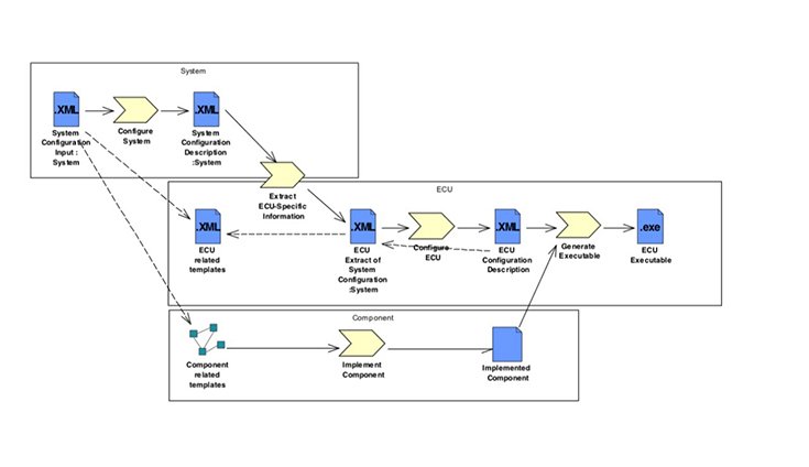
Design Steps from System- level execution to generation of ECU executable
How does the Virtual Functional Bus address the problem of effective communication between the modules?
In the industry, the database file which contains the requirements from the OEM is loaded in the Basic Software(BSW). THE BSW will have a GUI for configuration and once the GUI is configured the BSW will generate the code based on the AUTOSAR spec. The software developer basically develops a model and the code for the model will be generated using the BSW . The generated code will be an xml file. It is a generic code ( like a template). It may contain information like input comes through this port, output will go through this port. It will have dummy inputs. No logic will be present. The software developer has to build the logic. Only local variables may be used to develop the code as all the software modules may be sharing the memory as specified by the system level architecture ( the system architect could have defined that only a certain percentage of the memory should be used). The global variables may not be altered. The software developer will also have to specify the I/O, how information should be transferred ( information may be transferred through a float), he will also define the ports (read port , write port) etc. For example, Software component 1 may access software component 2 thorough port A Further, all the software modules will work independently. However, the memory is always limited. So the software designer cannot invoke any global variable and design the software, as the memory will always be limited. AUTOSAR will define the number of ports, which port should be used and the standards like say AUTOSAR 4.3 . The software developer can use the API of AUTOSAR 4.3 to call another module or access another port. Further, all the software components will share the same RAM memory. There is no physical bus. The whole process of accessing the memory, how the software components communicate thorough APIs is defined as Virtual Function Bus. The output will be generated as a C CODE or as a binary code if the supplier/TIER1 company decides to retain the IP of the software. But even a binary code is delivered to the OEM it will still work as the logic is written as per the standards defined by the AUTOSAR and system architect. The system architect will integrate all the coded and the binary code/ C code will work to serve the function/application.

 WhatsApp us